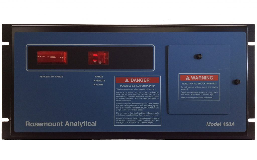
BECKMAN 400, BECKMAN 400A, ROSEMOUNT 400A TOTAL HYDROCARBON ANALYZER

This particular analyzer is one of RIGAS’ favorites to work on (i.e., repair).

Here is a list of some of our checks that we perform before we release your analyzer for shipment:

  1. Noise on range X1 should be minimal (±1 count)
  2. All ranges should be correlated (especially those with an optional range trim board)
  3. Response to certified calibration gas should be equal to or better than factory specifications
  4. When TP5 = 5 VDC then [a] the display reads 100.00, [2] analog output is either 100mV or 1V or 5V (depending on jumper configuration, [3] isolated current output = 20 mADC
  5. Analyzer is clean
  6. Insulation is re-glued
  7. Frayed wires are fixed
  8. Plexiglas is grounded
  9. A/C power switch leads are coated with “liquid electrical tape” to prevent inadvertant electrical shock to the end user
  10. Ribbon cables are pristine
  11. Rear terminal strip has a sticker that shows what functions are on what terminals
  12. Zero pot (potentiometer) is greater than 50% (the higher the number here, the less contamination in the analyzer tubing)
  13. It needs to look good again (paint job if necessary)
  14. Flame safety circuits MUST work properly
  15. Backpressure regulator works as designed (and controls at a very reliable value)
  16. There’s a bunch more, but we don’t want to bore you with the entire list!


Give us a try by calling us at 877-616-0600.

ROSEMOUNT 755, 755G, 755A, 755R PARTS LIST (ALSO BECKMAN)

Part Number Description Available?
632785CSS 755: Door board Y
638254 755: Alarm relay assy
638254RU 755: Alarm relay assy
L22-BA-2.0 755: Barry Mount vibration Y
S22-AA-2.2 755: Barry mount vibration Y
622356RU 755: Board Assy, Photocell
622356 755: Board Assy, Photocell Y
622351 755: Board, Connector Y
631773 755: BOARD, POWER SUPPLY Y
631773RU 755: BOARD, POWER SUPPLY Y
6A00236G01 755: Cable, detector upgrade
622443CSS 755: det/mag assy Y
622443 755: det/mag assy
656189RU 755: detector Y
632359 755: detector strip heater Y
6A00233G01 755: detector upgrade kit
861273 755: FAN (120V) case htr {*} Y
861649 755: Fuse, Thermal, 76°C{*} Y
656143 755: Kit, Detector Assy
50A0010R0 755: Kit, Source Lamp Y
616418 755: Kit, Source Lamp{*} Y
622422 755: MAGNET
876316 755: master board term 4 p {*} Y
193311 755: METER WITH BLANK SCALE
632358RU 755: paramagnetic detector
632358CSS 755: Paramagnetic detector RU Y
50A0001R0 755: plug tabs
616239 755: Source Lamp, bulb only(*)
861651 755: thermistor, 100K {*} Y
861651RU 755: thermistor, 100K RU Y
656189 755:DETECTOR OPTICAL BENCH KIT
7289A32 755A: Allen Wrench, 0.9mm Hex Y
95966A414 755A: Panel screw
50D0002R4 755A: Pressure comp interface
899495 755A: AD625, pressure comp {*} Y
7122A12 755A: Allen Wrench 0.035 inch Y
861467 755A: anti-vibration mounts{*}
661121 755A: baro interface bd{*}
661207 755A: barometric comp bracket
50D0003R1 755A: bracket, baro module
50B0001R0 755A: CABLE ASSY
632380 755A: CABLE ASSY {*}
50D0005R0 755A: det heater interface bd
622637RU 755A: detector kit
LCD5663R-27K 755A: LCD display, 6 seg
888302 755A: LCD display, 6 seg {*}
898365 755A: LCD driver chip {*}
50D0004R0 755A: M&C detector bracket
50D0002R0 755A: pressure comp interface
50D0002R3 755A: pressure comp interface
901068 755A: ribbon wire 4C {L} Y
882297 755A: U1 isolation driver {*}
901792 755R/951C: Backlight for LCD Y
652830 755R: Board Assy, Control
654022 755R: Display Assy (951C too) Y
654080 755R: Fan Assy, Case Heater{*} Y
901791 755R: LCD display, 6 seg Y

ROSEMOUNT 400A PARTS LIST (SIMILAR TO BECKMAN 400) (HYDROCARBON ANALYZER)

Part Number Description
25B0001R0 400: Power supply cover
25B0002R0 400: Temperature Controller
400A-2008-0001 400A, 120 VAC on alarm bus
898816 400A: range relay {*}
623983 400A: Range Select Board
9385K61 400A: Foam Insulation
25C0008R0 400A: Display driver
400A ANALYZER 400A: Rosemount Analyzer
25A0001R0 400: Glow plug / igniter
25C0001R0 400A light up procedure
25C0007R0 400A: 4-20 mADC board
400A-ALARM 400A: alarm module
25C0005R0 400A: cable 16 conductor
25C0009R0 400A: Door, Inside plexiglass
25C0004R0 400A: high range capillary
25C0003R0 400A: mixed fuel capillary
25C0002R0 400A: pure fuel capillary
620443RU 400A: RANGE SWITCH BD
400A-REPAIR 400A: repair of analyzer
620423-REPAIR 400A: Repair of Preamp Board
73659 400: Burner Tip Assembly
630375 400: Cap assy w/glow plug
73658 400: collector assy
73674 400: Electrode kit
617900 400: Glow plug / igniter (*)
834341 400: Lamp, Pilot {*}
643459 400: SS GAUGE, 5psig
6A00324G01 400A: Main Elect Bd Updated
656888 400A: Air restrictor blue dot
620428 400A: BOARD, AMPLIFIER *
621031 400A: CABLE, 16 COND
655178 400A: Door,Inside plexiglas{*}
620446 400A: Flame Out Bd (Obsolete)
656921 400A: high range capillary {*}
860918 400A: igniter toggle switch{*}
630669 400A: Mixed fuel restrict red
620423 400A: Preamp Board
620443 400A: RANGE SWITCH BD
898904 400A: reed relay {*}
904731 400A: reed relay 5V, 1A {*}
898861 400A: relay, 24v {*}
876447 400A: SPAN POT, 30K {*}
655171

OPM2000 PARTS LIST


Part Number Description
** BOARDS
1L03628G01 CPU BOARD ASSY
1L03394H01 REPLACED BY 1N04967G01
1N04967G01 RELAY OUTPUT & TERM. PANEL KIT
3D39097G01 ANALOG OUTPUT CARD, CRE
1N04956G02 GENERAL USER INTERFACE
1N04957G02 ADP CRU
3D39263G01 DETECTOR AMPLIFIER ASSY
3D39028G01 INTERCONNECT BOARD ASSY
1A97965H01 POWER SUPPLY, LAMP
9679D01G01 rs232/rs-232/422 PCB ASSY CONVERTER
3D39055G01 CRE/OPM DRIVER BOARD ASSY
4843B05G01 IO PLEXER ASSY
4843B05H02 INPUT MODULE, #IV5, 0-5V
4843B05H03 REPLACED BY 1A98478H01
1A98478H01 INPUT MODULE DUTEC #IAC5
4843B05H04 REPLACED BY 1A98479H01
1A98479H01 OUTPUT MODULE DUTEC #0AC5
** ELECTRICAL
4841B76H02 LAMP (replaced by 40B0011R0)
40B0011R0 LAMP, #L8008, frosted
1A97962H01 THERMOSTAT,
1A97964H01 REPL BY 1A97964H03
1A97964H03 HEATER, 120 VOLT, 300 WAT
4511C83H02 REPL BY 4511C83H01
4511C83H01 BLOWER MOTOR
3532B25H01 SWITCH, DIFF. PRESS.
** FILTERS
4841B92H01 REPL BY 4843B09H01
4843B09H01 FOAMEX FILTER, SIF 45 PPI
4841B92G01 (bad part number in manual)
4841B92H02 REPL BY 4843B09H02
4843B09H02 FOAMEX FILTER, SIF 60 PPI
4841B94H01 REPL BY 4843B11H01
4843B11H01 FILTER RETAINER
9884A16H02 REPLACED BY 9884A16H05
9884A16H05 FILTER, POLYURETHANE
9884A16H04 FILTER CARTRIDGE ASSY BLWMOTOR
1A99231G01 FILTER KIT
1A98248G01 SPARE PARTS KIT
** LCWs
4842B37G01 REPLACED BY, CONSULT RIGAS
4843B15G01 REPLACED BY, CONSULT RIGAS
1A98904G01 GLASS LCW RETROFIT KIT 3-10 FT
4848B50G02 LCW 1, REPLACED BY 40F0050R02
40F0050R02 LCW 1, Single element
4848B50G01 LCW 2, REPLACED BY 40F0050R01
40F0050R01 LCW 2, Multi-segment
1A99433G01 Temperature control retrofit kit
** MECHANICAL
3532B51H01 CHECK VALVE

25C0007R0 4-20 MADC ISOLATED OUTPUT BOARD (REPLACES OEM 620433 & 621023)

Description: This is an isolated signal analog output card used industry wide. The analyzer’s potentiometric output (DC volts) signal drives the signal for the 4-20 mADC card (usually 0VDC input = 4 mADC output & 5 VDC input = 20 mADC output). The term “isolated” refers to the fact that the output signal is not referenced to earth ground and is therefore much less susceptible to interference from other voltage sources. Milliamp signals are very useful when running long signal loops (on the order of tens of feet to thousands of feet long; note that total loop resistance has to be less than 850 ohms).

Where used: 400A,755,755A,755R,870

Static sensitive: This board is not very susceptible to ESD but handle it with some ESD protocols.

Replaces: Rosemount 620433 (in kit p/n: 621023)

Compatibility: RIGAS has released its compatible version of the OEM board. Some nice enhancements were included: [1] hook-type test points, [2] better labeling, [3] heat sinks, [4] zero & span potentiometers can dual configuration (i.e., adjustable from the top or from the front).

Please specify potentiometer type when ordering. Choices: [1] end adjust or [2] top adjust

Typical failure modes (after many years of service): [1] total failure: most likely due to the fullwave bridge rectifier or output opamp. [2] non-linearity: most likely due to the charge pump circuit. [3] inability to calibrate: most likely due to the charge pump circuit. [4] noisy output: output opamp is failing –or– input signal is noisy –or– board mounted isolated power supply(ies) are failing –or– loop resistance is very high –or– it could be that your mADC reader (DCS, DAS, etc) is misbehaving.

Repairable: Yes!  Call us at 877-616-0600 for an RMA number.

DESICCANT CARTRIDGE REGENERATION

RIGAS can save you money on desiccant cartidges by regenerating your saturated cartridge for half the cost of a new cartridge.  Although not all cartridges can be serviced, the popular 1647727 from Parker can.  This part number is used often in hydrogen generators for FIDS.  Send us your used cartridge and we will restore it to like-new.  Your desiccant cartridge will be returned to you in a moisture proof container ready for its next rotation.

TELEDYNE UNIVERSAL MOTHERBOARD SCHEMATIC C-31945 (MARKED UP FOR 316RA CONFIGURATION)

We spent a few hours trying to route signals through the backplane (motherboard) so now we have a marked up copy. We don’t have it digitized yet, so just call us and we’ll send you what we have.

Other 316RA schematics (available at Teledyne’s website):
* A-25686
* A-33140
* B-9051
* B-29602
* B-32152
* B-33129
* B-40393
* C-35087

The 316RA is a trace oxygen analyzer (polarographic; chemical cell; fuel cell). It seems well built. It has wide acceptance of industrial customers.

ROSEMOUNT 654062 OR 654943, CHILLER HOUSING (THERMOCOOLER FOR PMT (PHOTOMULTIPLIER TUBE))

These coolers/chillers are probably hard to come by … and if you do find one, it is most likely VERY EXPENSIVE. We can fix these. The usual failure mode is that your 951A (LoTempCo version) or 951C starts misbehaving and it seems to misbehave based on room temperature. It could also be impossible to zero or maintain a good zero. What is probably happening is your PMT (655168) is no longer being maintained at 6°C and that is creating a significant ‘dark current’ in the PMT. Or equally bad is that it is close to 6°C but the temperature is not stable, so getting a good zero on the instrument is fruitless.

Another failure symptom is scorched or burned wires associated with the chiller circuit. The chiller is fed by a high current DC power supply (roughly 14 VDC); when the Peltier chips go bad, more current is required to achieve the cooling required and ultimately, there is so much current that the wire limitations are exceeded (especially when you factor in Rosemount’s use of 18awg high current wire). Look at the J16 plug and the J15 plug on the Power Supply Board. Check the terminations on the terminal strip on the side of the high current power supply too.

The cooler is built with a metal can liner that surrounds the PMT; the metal liner is thermally connected to two Peltier chips (or elements); the Peltier chips are thermally connected to the aluminum fin housing that you see when you open the instrument. These components are all potted in Stryofoam insulation.

Check the continuity of the red and black wires going to the chiller unit. New Peltier chips will read about 2 ohms in one direction and -2 ohms in the other direction (the negative reading come from the battery effect of the Peltier chips; essentially these are a million thermocouples amassed together … and thermocouples are little batteries in the presence of heat).

Our repair consists of extracting the old Peltier cells, installing new ones, repotting everything, checking the feedback thermistor, and testing the final assembly.

Call us for more information.

ROSEMOUNT 400A PREAMPLIFIER BOARD 620423

Operation (excerpted from 400A manual): The ionization current generated by the burner is measured by an electrometer preamplifier located adjacent to the burner assembly. This small current is amplified and transformed into a signal voltage that is then further amplified by a post amplifier before being converted to a digital display suitable for direct data presentation. To cover the required dynamic range, the amplifier is provided with two gain ranges that differ by a factor of 100. Output voltage from the preamp is a precise function of ionization current.  The most sensitive gain range includes a trim adjustment so that inter-range correlation can be obtained over the entire signal span.

A buffer signal offering unity gain and noise filtration provide a low output impedance to drive the signal cable and post amplifier circuits on the main circuit board. Selection of the low or high range feedback resistors is made by relay K1 on the preamplifier board.  A variable offset current is injected into the summing node of the electrometer amplifier to compensate for background offset current. These currents influence the measurement procedure, and a variable voltage at the front panel allows the user to visually cancel these currents during the calibration procedure. Background current is due to unavoidable traces of carbonaceous material introduced into the burner flame by the fuel gas and air.

Operation comments by RIGAS: K1 is a N.O. relay (shelf state).  When open (de-energized), maximum feedback resistance is applied to U2 (first stage) thus resulting in maximum gain or high sensitivity.  When K1 is closed (energized by +5 VDC when range X100, X250, or X1000 is selected) then R17 is placed in parallel with R18 resulting in less feedback resistance and thus less gain or less sensitivity.

Jumper E1-E2-E3 should be in the E1-E2 position.  E2-E3 is a factory test position but could be used to determine the exact amount of amplifier offset or burner contamination since all Zero Compensation would be removed from the circuit.

Jumper E4-E5 should be in place.  This allows the polarizing voltage to be grounded out during lighting (when switch is set to “ignite”).

Typical Failures:

  • Glass encapsulated, high ohmage, precision resistors get dirty. Dirt conducts so the more dirt, the less ohmage.
  • Glass capacitors. Dirt conducts so more dirt changes capacitance.
  • Coax cable breaks down (signals get noisy)
  • Jumper wires get frayed, brittle, and break
  • Opamps (operational amplifiers) fail (use list of expected voltages here)
  • Purge / ignite switch fails
  • 3 VAC transformer fails
  • Interconnecting ribbon cable gets pinched and fails
  • Burner contact assembly fails (this is a ghost [‘looks’ like] a preamp board failure)
  • Burner collector ring connection fails (this is a ghost [‘looks’ like] a preamp board failure)
  • Burner temperature sensor fails (fuel solenoid won’t stay latched after lighting ‘pop’)

Other information:

RIGAS built a special resistor pack to simulate the ion current developed by burning hydrocarbons.  We have six 500 gigaohms resistors in series to mimic the very low ion current (3 x 10-11 amps) in the burner (remember that a 90 VDC polarizing voltage is applied at this end of the circuit). This helps us determine if noise is coming from the burner chamber proper or the preamp board.

Schematic 620424 (with RIGAS embedded notes)

List of expected voltages

Simplified electronic calibration

Remember:

  • When the Zero pot is up near 10 (full CW) that is GOOD! That means that there is minimal contamination to overcome with a bias signal.
  • Failure to light is usually a fuel/air ratio problem (usually not enough fuel getting to the chamber)
  • Failure to light could be as simple a s blown glow-plug
  • The 400A is a PERCENTAGE readout analyzer and a TOTAL HYDROCARBON analyzer
    • the display reads a percentage of your calibration gas numbers
    • any hydrocarbon will read out on this analyzer.  If you calibrate with 20 ppm methane and inject 5 ppm of butane, you’ll get the same response
    • Click here for the 400A calculator spreadsheet

Normal maintenance:

  • Replace old jumper wires & their connectors
  • Replace coax
  • Clean resistors and capacitors
  • Replace DIP socket with gold plated DIP socket
  • Replace opamps with latest low-noise opamps
  • Test

ROSEMOUNT 400A COMPONENTS GET HOT ON MAIN ELECTRONICS BOARD

Affected components:

  • 620428 Rosemount 400A Main Electronics Board (schematic 620429)
  • 620433 Rosemount 400A Isolated 4-20 maDC board (schematic 620434) … (item is now obsolete by OEM … replaced by RIGAS25C0007R0)

Situation: The analyzer appears to operate normally (mostly anyway). U13 seems to get very hot (so does U4 [voltage output buffer amplifier]) and there is a 620433 (V/I option board) installed. Also, when attempting to light the analyzer, the analog display will overrange and remain overranged until the power is cycled on the analyzer (TP-5 will be saturated at about 13 vdc).

Problem: someone has employed the E1-E2 and E3-E4 jumpers and this is causing a nasty feedback loop that U13 is trying to compensate for. When the analyzer goes upscale (it always spikes during startup) this causes the analog signal to spike which, in turn, causes the 4-20 maDC card to spike. The 4-20 signal being fed back to U13 has now locked it railed high.

Resolution: remove the 4-20 maDC board or remove the E1-E2 and E3-E4 jumpers.

Other info: U12 & U13 & U4 are µA714 opamps (a.k.a., uA714); they can be replaced with OP07 or OP77 or OP177.