ROSEMOUNT GPC-1500 & GPC-1500A VERY OBSOLETE … CONTACT ESYS

ESYS has expertise with this multi-loop controller.  It has been used in various applications; the one it was designed for is boiler control.  The application that we used it on (and serviced it on) was CEMS (continuous emissions monitoring).

On the CEMS application, the controller handled analog rescaling (for daily automatic re-calibration offsets), solenoid valve control, and some limited threshold/alarm logic.

If you’re looking for a quick fix – try replacing the battery.  That could cure a whole host of problems.

Rosemount 400A is officially obsolete by OEM. No SUPPORT or PARTS from OEM. RIGAS plans to support for the next 10+ years.

As of September 30, 2023, the Rosemount 400A has been officially obsoleted by OEM (Emerson – Rosemount Analytical) with NO OEM PARTS or FACTORY SUPPORT.  There is good news though;  RIGAS plans to support this analyzer for at least the next ten (10) years, and maybe longer.  If you are an end-user, you can help us help you by NOT throwing away good components (boards, regulators, etc.).  Everything is repairable.  Here are a few examples:

1. Main Electronics Board (pre-2009 vintage) – rarely fails. Shipping sometimes causes the big transformer to be ripped off the board

Fixable. We have new transformers.

2. 4-20 mADC card gets noisy or fails outright

Usually a few capacitors dry out causing the “charge pump” to misbehave. We replace the capacitors and fully test the board (includes linearity checks).

3. Backpressure regulator – the rubber diaphragm dries out, becomes brittle, and then it doesn’t regulate pressure very well.

We install a new diaphragm and relap the valve seat; the result is near PERFECT operation (very little seat leakage and great pressure control).

4. Ribbon cables – they get pinched or scraped.

We build our own cables.

5. Sample capillary – it gets clogged over time causing a lack of sensitivity.

It can be cleaned but we’d rather just replace the old capillary (and possibly reuse your old fitting);  capillaries are just soldered into a Parker-Hannifin, tube-end reducer, stainless steel fitting using a Silver bearing solder.

Additionally, if your application is unique, we can build a unique capillary.

6. Thermal insulation – it becomes unglued.

We replace the insulation where needed and/or reglue the old insulation.

7. Burner jet gets fouled causing false flame problems or noisy readings.

We make our own jets.

8. Burner contact gets old and brittle, and eventually breaks causing a total loss of analyzer functionality.

We make our own burner contacts (a.k.a., Hot Dogs).

So, in other words, just about everything is repairable.  So, let’s partner up and keep your analyzer running!!!

A side note:  Emerson-Rosemount does NOT have a replacement analyzer for the 400, 400A series.  RIGAS is toying with the idea of building a replacement analyzer and calling it the RIGAS 400R.  It will be VERY similar to the Rosemount 400A but maybe a little easier to operate.  We plan to change the display to read “ppm” rather than percent (%) of scale.  It will also have built in diagnostics for those key parameters that we always ask you about when you call in for technical support.  In the meantime, RIGAS does recommend the Teledyne 4020 THC analyzer (or one of the sister units, like the 4040).

BECKMAN 400, BECKMAN 400A, ROSEMOUNT 400A TOTAL HYDROCARBON ANALYZER

This particular analyzer is one of RIGAS’ favorites to work on (i.e., repair).

Here is a list of some of our checks that we perform before we release your analyzer for shipment:

1. Noise on range X1 should be minimal (±1 count)

2. All ranges should be correlated (especially those with an optional range trim board)

3. Response to certified calibration gas should be equal to or better than factory specifications

4. When TP5 = 5 VDC then [a] the display reads 100.00, [2] analog output is either 100mV or 1V or 5V (depending on jumper configuration, [3] isolated current output = 20 mADC

5. Analyzer is clean

6. Insulation is re-glued

7. Frayed wires are fixed

8. Plexiglas is grounded

9. A/C power switch leads are coated with “liquid electrical tape” to prevent inadvertant electrical shock to the end user

10. Ribbon cables are pristine

11. Rear terminal strip has a sticker that shows what functions are on what terminals

12. Zero pot (potentiometer) is greater than 50% (the higher the number here, the less contamination in the analyzer tubing)

13. It needs to look good again (paint job if necessary)

14. Flame safety circuits MUST work properly

15. Backpressure regulator works as designed (and controls at a very reliable value)

16. There’s a bunch more, but we don’t want to bore you with the entire list!


Give us a try by calling us at 877-616-0600.

ROSEMOUNT 400A PARTS LIST (SIMILAR TO BECKMAN 400) (HYDROCARBON ANALYZER)

Part Number Description
25B0001R0 400: Power supply cover
25B0002R0 400: Temperature Controller
400A-2008-0001 400A, 120 VAC on alarm bus
898816 400A: range relay {*}
623983 400A: Range Select Board
9385K61 400A: Foam Insulation
25C0008R0 400A: Display driver
400A ANALYZER 400A: Rosemount Analyzer
25A0001R0 400: Glow plug / igniter
25C0001R0 400A light up procedure
25C0007R0 400A: 4-20 mADC board
400A-ALARM 400A: alarm module
25C0005R0 400A: cable 16 conductor
25C0009R0 400A: Door, Inside plexiglass
25C0004R0 400A: high range capillary
25C0003R0 400A: mixed fuel capillary
25C0002R0 400A: pure fuel capillary
620443RU 400A: RANGE SWITCH BD
400A-REPAIR 400A: repair of analyzer
620423-REPAIR 400A: Repair of Preamp Board
73659 400: Burner Tip Assembly
630375 400: Cap assy w/glow plug
73658 400: collector assy
73674 400: Electrode kit
617900 400: Glow plug / igniter (*)
834341 400: Lamp, Pilot {*}
643459 400: SS GAUGE, 5psig
6A00324G01 400A: Main Elect Bd Updated
656888 400A: Air restrictor blue dot
620428 400A: BOARD, AMPLIFIER *
621031 400A: CABLE, 16 COND
655178 400A: Door,Inside plexiglas{*}
620446 400A: Flame Out Bd (Obsolete)
656921 400A: high range capillary {*}
860918 400A: igniter toggle switch{*}
630669 400A: Mixed fuel restrict red
620423 400A: Preamp Board
620443 400A: RANGE SWITCH BD
898904 400A: reed relay {*}
904731 400A: reed relay 5V, 1A {*}
898861 400A: relay, 24v {*}
876447 400A: SPAN POT, 30K {*}
655171

25C0007R0 4-20 MADC ISOLATED OUTPUT BOARD (REPLACES OEM 620433 & 621023)

Description: This is an isolated signal analog output card used industry wide. The analyzer’s potentiometric output (DC volts) signal drives the signal for the 4-20 mADC card (usually 0VDC input = 4 mADC output & 5 VDC input = 20 mADC output). The term “isolated” refers to the fact that the output signal is not referenced to earth ground and is therefore much less susceptible to interference from other voltage sources. Milliamp signals are very useful when running long signal loops (on the order of tens of feet to thousands of feet long; note that total loop resistance has to be less than 850 ohms).

Where used: 400A,755,755A,755R,870

Static sensitive: This board is not very susceptible to ESD but handle it with some ESD protocols.

Replaces: Rosemount 620433 (in kit p/n: 621023)

Compatibility: RIGAS has released its compatible version of the OEM board. Some nice enhancements were included: [1] hook-type test points, [2] better labeling, [3] heat sinks, [4] zero & span potentiometers can dual configuration (i.e., adjustable from the top or from the front).

Please specify potentiometer type when ordering. Choices: [1] end adjust or [2] top adjust

Typical failure modes (after many years of service): [1] total failure: most likely due to the fullwave bridge rectifier or output opamp. [2] non-linearity: most likely due to the charge pump circuit. [3] inability to calibrate: most likely due to the charge pump circuit. [4] noisy output: output opamp is failing –or– input signal is noisy –or– board mounted isolated power supply(ies) are failing –or– loop resistance is very high –or– it could be that your mADC reader (DCS, DAS, etc) is misbehaving.

Repairable: Yes!  Call us at 877-616-0600 for an RMA number.

TELEDYNE UNIVERSAL MOTHERBOARD SCHEMATIC C-31945 (MARKED UP FOR 316RA CONFIGURATION)

We spent a few hours trying to route signals through the backplane (motherboard) so now we have a marked up copy. We don’t have it digitized yet, so just call us and we’ll send you what we have.

Other 316RA schematics (available at Teledyne’s website):
* A-25686
* A-33140
* B-9051
* B-29602
* B-32152
* B-33129
* B-40393
* C-35087

The 316RA is a trace oxygen analyzer (polarographic; chemical cell; fuel cell). It seems well built. It has wide acceptance of industrial customers.

ROSEMOUNT 400A PREAMPLIFIER BOARD 620423

Operation (excerpted from 400A manual): The ionization current generated by the burner is measured by an electrometer preamplifier located adjacent to the burner assembly. This small current is amplified and transformed into a signal voltage that is then further amplified by a post amplifier before being converted to a digital display suitable for direct data presentation. To cover the required dynamic range, the amplifier is provided with two gain ranges that differ by a factor of 100. Output voltage from the preamp is a precise function of ionization current.  The most sensitive gain range includes a trim adjustment so that inter-range correlation can be obtained over the entire signal span.

A buffer signal offering unity gain and noise filtration provide a low output impedance to drive the signal cable and post amplifier circuits on the main circuit board. Selection of the low or high range feedback resistors is made by relay K1 on the preamplifier board.  A variable offset current is injected into the summing node of the electrometer amplifier to compensate for background offset current. These currents influence the measurement procedure, and a variable voltage at the front panel allows the user to visually cancel these currents during the calibration procedure. Background current is due to unavoidable traces of carbonaceous material introduced into the burner flame by the fuel gas and air.

Operation comments by RIGAS: K1 is a N.O. relay (shelf state).  When open (de-energized), maximum feedback resistance is applied to U2 (first stage) thus resulting in maximum gain or high sensitivity.  When K1 is closed (energized by +5 VDC when range X100, X250, or X1000 is selected) then R17 is placed in parallel with R18 resulting in less feedback resistance and thus less gain or less sensitivity.

Jumper E1-E2-E3 should be in the E1-E2 position.  E2-E3 is a factory test position but could be used to determine the exact amount of amplifier offset or burner contamination since all Zero Compensation would be removed from the circuit.

Jumper E4-E5 should be in place.  This allows the polarizing voltage to be grounded out during lighting (when switch is set to “ignite”).

Typical Failures:

1. Glass encapsulated, high ohmage, precision resistors get dirty. Dirt conducts so the more dirt, the less ohmage.

2. Glass capacitors. Dirt conducts so more dirt changes capacitance.

3. Coax cable breaks down (signals get noisy)

4. Jumper wires get frayed, brittle, and break

5. Opamps (operational amplifiers) fail (use list of expected voltages here)

6. Purge / ignite switch fails

7. 3 VAC transformer fails

8. Interconnecting ribbon cable gets pinched and fails

9. Burner contact assembly fails (this is a ghost [‘looks’ like] a preamp board failure)

10. Burner collector ring connection fails (this is a ghost [‘looks’ like] a preamp board failure)

11. Burner temperature sensor fails (fuel solenoid won’t stay latched after lighting ‘pop’)

Other information:

RIGAS built a special resistor pack to simulate the ion current developed by burning hydrocarbons.  We have six 500 gigaohms resistors in series to mimic the very low ion current (3 x 10-11 amps) in the burner (remember that a 90 VDC polarizing voltage is applied at this end of the circuit). This helps us determine if noise is coming from the burner chamber proper or the preamp board.

Schematic 620424 (with RIGAS embedded notes)

List of expected voltages

Simplified electronic calibration

Remember:

1. When the Zero pot is up near 10 (full CW) that is GOOD! That means that there is minimal contamination to overcome with a bias signal.

2. Failure to light is usually a fuel/air ratio problem (usually not enough fuel getting to the chamber)

3. Failure to light could be as simple a s blown glow-plug

4. The 400A is a PERCENTAGE readout analyzer and a TOTAL HYDROCARBON analyzer

the display reads a percentage of your calibration gas numbers

any hydrocarbon will read out on this analyzer.  If you calibrate with 20 ppm methane and inject 5 ppm of butane, you’ll get the same response

Click here for the 400A calculator spreadsheet

Normal maintenance:

1. Replace old jumper wires & their connectors

2. Replace coax

3. Clean resistors and capacitors

4. Replace DIP socket with gold plated DIP socket

5. Replace opamps with latest low-noise opamps

6. Test

ROSEMOUNT 400A COMPONENTS GET HOT ON MAIN ELECTRONICS BOARD

Affected components:

1. 620428 Rosemount 400A Main Electronics Board (schematic 620429)

2. 620433 Rosemount 400A Isolated 4-20 maDC board (schematic 620434) … (item is now obsolete by OEM … replaced by RIGAS25C0007R0)

Situation: The analyzer appears to operate normally (mostly anyway). U13 seems to get very hot (so does U4 [voltage output buffer amplifier]) and there is a 620433 (V/I option board) installed. Also, when attempting to light the analyzer, the analog display will overrange and remain overranged until the power is cycled on the analyzer (TP-5 will be saturated at about 13 vdc).

Problem: someone has employed the E1-E2 and E3-E4 jumpers and this is causing a nasty feedback loop that U13 is trying to compensate for. When the analyzer goes upscale (it always spikes during startup) this causes the analog signal to spike which, in turn, causes the 4-20 maDC card to spike. The 4-20 signal being fed back to U13 has now locked it railed high.

Resolution: remove the 4-20 maDC board or remove the E1-E2 and E3-E4 jumpers.

Other info: U12 & U13 & U4 are µA714 opamps (a.k.a., uA714); they can be replaced with OP07 or OP77 or OP177.

RIGAS – TELEDYNE LIGHTHAWK 560: QUARTERLY AUDIT PROCEDURE

Quarterly audits should be simple … thorough … but still as simple as possible. Unlike the Teledyne procedure (see below), our method is fully compliant with EPA Method 203, EPA Procedure 3, ASTM D 6216-98, and 40 CFR part 60.

This is a snippet of RIGAS’ procedure:

1. record the serial numbers
2. challenge the PLCF
3. note the Fault indicators
4. record current readings (including Dust Compensation)
5. record current calibration values
6. record calibration set points
7. record LED drive current
8. check purge air system (replace air filters as necessary [be careful not to disturb the dust, that will alter your EPA data])
9. align
10. perform a dust accumulation test (which cleans the optical surfaces as a PM measure)
11. manual calibration cycle check
12. record new Dust Compensation value
13. install Cal Kit Fixture
14. do NOT perform Background Set
15. do NOT perform Normal Set
16. do NOT remove Cal Kit Fixture
17. do NOT perform Zero Set
18. check Cal Zero value
19. do NOT manual calibration cycle check
20. analog output check
21. perform Calibration Error Test
22. record all EPA data from the data historian (or chart recorder)
23. clean the unit (outside)
24. complete the EPA compliant report

Please contact us if you’re looking for a vendor to do quality EPA audits, analyzer preventive maintenance, analyzer repair (on site or in our depot),parts, or telephone technical support. We also have Teledyne LightHawks to rent.

PRESSURE OR FLOW? A DISCUSSION ABOUT SAMPLE DELIVERY TO A PARTICULAR ANALYZER TYPE

If asked how we would supply a sample source to a ‘pressure sensitive’ analyzer, we would tell you to control the source pressure and not throttle the source pressure/flow.

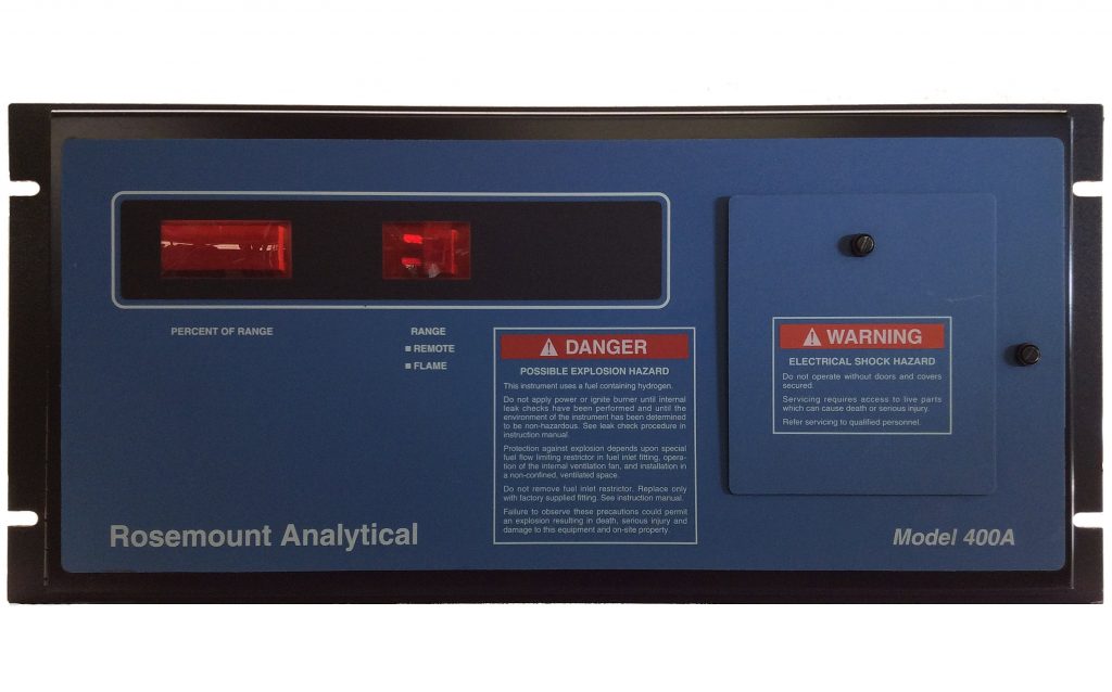
We’re in the “control the source pressure” camp and not of the “throttle the source flow” camp.  The Rosemount 400, 400A, 951A, 951C, 951E, NGA-FID1, NGA-HFID, and NGA-CLD series analyzers are sample pressure dependent analyzers, that is, this type of analyzer utilizes sample source pressure to create the motive force for sample to flow through a restrictor or capillary (and, in rare instances, through a mass flow controller).  In order for this type of analyzer to determine the % (percent) or PPM (parts per million) concentration of its sample, it requires a stable pressure at key pneumatic junctions within the analyzer itself.  Typically, this junction is near the sensing element and is usually flow controlled by a capillary tube or precision restrictor. To ensure that this pneumatic junction is controlled at some value, 3 psig for instance, a back pressure regulator (BPR) is employed.

This is how it is supposed to function: when sample is applied, the pressure within the analyzer builds up until it reaches the control point (a.k.a., set point) of the BPR; if the pressure continues to build, the BPR bleeds the excess pressure off to a vent header or waste dump.  The bleed off is sometimes referred to as bypass flow.  This action by the BPR controls the pneumatic junction at a predefined value … as long as there is excess source pressure.

If we control the source pressure (i.e., sample pressure) then we can control the bypass rate as well, simply by changing the source pressure, that is, you control the delta-P (delta-pressure) between the two systems … and you get the benefit of great analyzer accuracy simply due to more accurate control of the key pneumatic junction.

Here are examples (assume that your analyzer runs at 3 psig internal sample pressure):


Example 1:

1. Source pressure = 3psig

2. Analyzer is happy (that is, the capillary is maintained perfectly at 3psig by either the internal backpressure regulator [BPR] or the external forward pressure regulator so the THC calibration is valid)

3. But there is no bypass flow so response time to process excursions is VERY poor.


Example 2:

1. Source pressure = 5 psig

2. Analyzer is happy (that is, the capillary is maintained perfectly at 3 psig by the internal backpressure regulator [BPR] so the THC or NOx calibration is valid)

3. and because there is a pressure delta between source pressure and control pressure, there is significant bypass flow (within the capabilities of the BPR) so response time to process excursions is good

4. let’s assume that this creates 1200 cc/min of sample bypass flow (this assumption used in the next example)


Example 3:

1. Source pressure = 4 psig

2. Analyzer is happy (that is, the capillary is maintained perfectly at 3 psig by the internal backpressure regulator [BPR] so the THC calibration is valid)

3. because there is a pressure delta between source pressure and control pressure, there is significant bypass flow (within the capabilities of the BPR) so response time is OK

4. we probably lost half of our bypass from the previous example so let’s assume that this creates 600 cc/min of sample bypass

5. We’re still OK.  No loss of accuracy. Response time to process excursions might be an issue on some systems.


Example 4:

1. Source pressure = 25 psig

2. Analyzer is NOT happy. The internal backpressure regulator [BPR] is bypassing at its maximum rate (with a nasty “singing” sound) and has lost control of the 3 psig at the sample capillary so the THC or NOx calibration is NOT valid).

3. But there is significant bypass flow so response time is good … it’s just not giving us valid readings!

4. All process readings will read much higher than normal, and thus, inaccurate.


This might be a good time to talk about regulators and back pressure regulators. It should be noted that as source pressure climbs from setpoint to the end of the control band of the regulator, there will be a slight upward creep of the control pressure value; this in turn affects the key pneumatic junction and the analyzer’s calibration curve. This has to do with the internal operation of the regulator.  In order to correct for something like this, you might have to invest in a digital controller and I/P module to control the dome loading of a specially designed regulator (one that controls pressure mechanically but will also accept an external pneumatic signal to bias its setpoint one way or another).

Some companies throttle the inlet and ‘hope’ that the capillary is maintained at the correct pressure.  You ‘could’ assume you have positive control of the capillary pressure by virtue of the fact that there is bypass flow.  But we’ve seen significant interaction between a throttled source and the internal control pressure (BPR); so much interaction that we don’t endorse this method of control.  It’s a method of control that will not yield the most stable calibrations or process readings.  So if you’re looking to get superior accuracy, control the source pressure and let the delta pressure (D/P) control the bypass rate.

Attempting to control the bypass rate at the back of the analyzer at the analyzer’s bypass exhaust port is very bad. This will essentially take the internal BPR’s control out of the equation … you won’t have any positive control of the pressure at the capillary head … so your calibrations will be at the whim of the source pressure (or source flow … which in turn creates a pressure).

We’ve always wanted to make YouTube video of this and put it out there to dispel all of the misinformation.   Watch for its release which will star Rachel Ward (Dead Men Don’t Wear Plaid) as Juliet.

Call us at 877-616-0600 if you want the verbal version!  (Just in case the written version doesn’t make any sense!)