Some of the activities that we perform on your analyzer include replacing the restrictors (and/or capillary). We’ve adopted the “Teledyne API” method of installing good restrictors but not ‘exact’ restrictors. By that I mean, we buy restrictors that meet a small tolerance range, but each restrictor behaves just a little different from the other. Rather than tossing out restrictors that are not EXACTLY on target, we install them in your analyzer, adjust the upstream source pressure to achieve the desired results, and then create a label (or placard) that says what pressures we tuned the analyzer to.
Let’s do a “for instance” discussion. So, under the old way of thinking, the 400A had to run at 15 psig for air, and 25 psig for fuel. When it wouldn’t light or stay lit at 25 psig fuel, you blamed the restrictor(s) (logically), and ordered a new one for about $500. Under “our” way (the Teledyne API way), your analyzer can operate at any pressure that works easily with the physical characteristics of the restrictor that is installed. AND, we’ll give you assistance to adjust the baseline pressure when the restrictor begins to show signs of fouling. Case in point:
1. Your 400A needs to be serviced
2. You send it to RIGAS for repair / overhaul
3. We find that:
• the air restrictor flows weak at 400 cc/min @ 15 psig but flows at specification at 18 psig . . . we’re not going to replace this ‘good’ working restrictor
• the fuel restrictor flows weak at 60 cc/min @ 25 psig but flows at specification at 30 psig . . . this is the top end of your pressure gauge so we need to replace the restrictor
4. We install a new fuel restrictor that performs nicely at 20 psig
5. We calibrate your analyzer at these new pressure values:
• air = 18 psig
• fuel = 20 psig
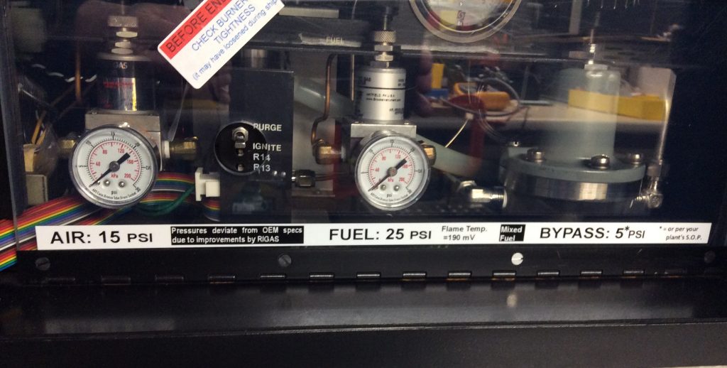
6. We affix our calibration sticker (see picture below)
7. We affix our optimized pressure settings sticker (that says that these pressure settings override the OEM’s pressure settings from the manual)
8. We send your analyzer back to you . . . and it performs marvelously for five to ten years
9. If necessary, add a little air (that is, adjust the pressure regulator higher)
10. If necessary, add a little fuel (that is, adjust the pressure regulator higher)
• On this one, look at burner temperature. We usually find that 60 to 120 mV on the Flame Temperature signal works best. 60mV is hot but not too hot. 120mV is a somewhat cool flame temperature but not too cool.
► On older analyzers (120vAC version) the flame signal can be read at TP13 (use TP8 as ground reference).
► On newer analyzers (120vAC version but with an internal 24 vDC power supply) the flame signal can be read at TP3 (use TP15 as ground reference).
• And if you’re wondering, the flame safety circuits (some call it “flame confirmation”) trip at 1000mV as it heats up and 1200mV as it cools down
Discussion: there’s actually nothing magical about Rosemount’s firm (sometimes rigid) stance on exactly 15 psi for air and exactly 25 psi for fuel. It really boils down to what settings are optimum for this (your) particular and unique analyzer. And ‘yes’, unique applies to every analyzer ever built as each restrictor flows just a little different than another; each thermistor temperature sensor responds just a little different from another; so, your analyzer may ‘look’ like every other 400A but in reality, it’s not ‘exactly’ the same. There’s another good analyzer manufacturer that subscribes to this thinking (we actually copied their policy), that is, every analyzer that they sell gets a sticker that defines the optimum settings that the technician doing final assembly and testing empirically determined. By you (the end user/customer) adopting this methodology with us, you’ll save on your operating costs. Why? Because you won’t be buying needless parts when, for instance, the fuel restrictor fouls a little bit. You’ll recognize the symptom and simply increase the regulator pressure to compensate for the minute fouling. You’re welcome.
A safety note: there is one restrictor that needs to be maintained ‘at or below’ its design specification, that being the bulkhead fuel restrictor (located upstream of the fuel shutoff solenoid). This restrictor is there to prevent a major fuel leak within the analyzer (fuel solenoid compromised, fuel line cracked, fitting loose, etc.) from creating an explosive mixture. This may be the most critical component in the FM (Factory Mutual) certification. Please don’t bypass this restrictor element. This restrictor can foul significantly before it impacts analyzer operation; and even if it does foul, just increase source pressure from the requested 45 psig to 50 psig (or whatever seems to alleviate the problem). The bulkhead restrictor fouling can be loosely determined by observing the fuel pressure response when you go to light the analyzer. Normal operation: go to “Purge” … the pressure jumps up to 18 psig fairly quickly (almost instantaneously) then gradually reaches the target pressure. Fouled operation: go to “Purge” … the pressure maybe jumps up to 10 psig fairly quickly (almost instantaneously) then gradually reaches attempts to reach the target pressure but never does. By the way, the “fouled operation” description ALSO applies to a leak downstream (or upstream) of the pressure regulator so ALSO check for fuel leaks.
Keywords: Rosemount 400A troubleshooting RIGAS enhancements TP-13 TP-8 TP-3 TP-15