Rosemount® NGA-CLD

Description

Rosemount® NGA-CLD

As of 2023, we no longer service the NGA-CLD. However, we are able to provide over-the-phone technical support on a per hour basis.

General

Analyzer overview/Theory of operation:  [later]

History

The NGA modular analyzer “shoebox” concept was developed in the 1990’s by the LaHabra / Anaheim division of Rosemount Analytical.  Rosemount made a universal platform that acted as the gateway (control) to all of the ‘blind’ physics modules that may be attached to it.  The physics (shoebox analyzers) ran the gambit of NDIR, paramagnetic, FID, HFID, Wet CLD, and CLD (chemiluminescence).  By far, the CLD module is the most compact of the analyzers and the hardest to work on (in my opinion).

Over the years the NGA2000 morphed in to the MLT (Rosemount Germany) … and then in circa 2021, Rosemount (Hasselroth) Germany was shuttered (closed).

As of this writing November 17, 2023 the NGA-CLD analyzer status is NLA (no longer available).   However, RIGAS can still get most parts for the NGA-CLD.

Documentation

[later] Analyzer datasheet – Downloadable

[later] Analyzer manual – Downloadable


Drawings

[later] Installation detail/Footprint

[later] Front Panel

[later] Back Panel

[later] Flow diagram

[later] I/O – Interconnect diagram

Parts

[later] List of parts common for service/rebuilds

[later] List of parts common for repairs/replacements

Troubleshooting

CLD (NOx analyzer) Troubleshooting

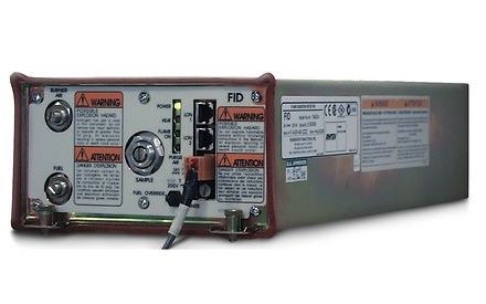
If you’ve stumbled on to this FAQ, you must have a Rosemount NGA-2000 CLD analyzer to measure NOX either dry or wet (referring to the WCLD version).   The detector portion of this analyzer is OEM p/n: 659754 (obsolete) and is sold by us under this part number:  35K0104R0.   It is the same OEM detector and fully compatible with your NGA-2000 or uCEMS.

I’d like to point out that this detector assembly is COMPLETELY repairable and should never be chucked in to the dumpster.  Here’s why:

  • If the capillary gets clogged … unclog it or solder in a new one
  • If the heaters fail open … replace the heaters
  • If the resettable fuse fails open … replace the fuse
  • If the barrier window gets cracked/busted … replace the window
  • If the temperature sensor goes bad … replace it
  • If the reaction chamber leaks … replace the bad seal (or both seals)
  • If a pin breaks off or a wire opens in the harness … fix the harness
  • If the metal barrel rusts through … this has never happened, but there’s always a first time … replace the housing
  • If the photosensor gets weak or dies completely … replace the sensor*          (* this is the most challenging aspect as the OEM wants about $8000 for this chip; and, most of the time, it’s the barrier window that gets clouded/stained from the ozone-NO reaction; we don’t change out very many sensor chips).
  • If the photosensor won’t cool down to 1°C, it might be a bad Peltier section of the chip -or- most likely, it’s a bad Darlington Pair power transistor (mounted on the aluminum divider panel).

We’ve been fixing about two of these per year for the past 20 years.  Don’t listen to the rumors that you can’t procure a NGA-2000 CLD detector assembly, we can get them or repair them.

The designer of this analyzer failed on two major points:

  1. He specified all sample tubing to be 1/8″ OD.  This is OK for some parts of the internal gas handling system but not for all parts of the sample tubing.
  2. He did not include a flow restrictor at the sample inlet.

Discussion (later)

Fix / upgrade / resolution:

  1. Change the reaction chamber exhaust tubing to 1/4″ OD Versillon or Tygon or Neoprene tubing.  Also change the BPR exhaust lines to 1/4″ OD tubing.
  2. Install a special, modified (with embedded restrictor), adapter at the sample inlet (4-4 TRBZ-SS or 2-4 TRBZ-SS) at the inlet (it attaches directly to the OEM’s SAMPLE INLET port).  RIGAS makes these on demand.
  • Sample pressure: 5 psig*    (* but can be anything that gives you the desired calibration results; the factory calibrates the capillaries for a 5 PSIG sample head pressure.  And because sample flow is controlled by a capillary, there is no danger of over pressurizing the reaction chamber.  However, excess sample pressure will, at some point, exceed the capabilities of the BPR (back pressure regulator) and control of sample pressure will be nonexistent).     NOTE: some customers had a limited sample pressure so the OEM configured many CLDs to run on 2 psig (internal) sample pressure; see below).
  • [opt] Sample pressure: 2 psig*    (* but can be anything that gives you the desired calibration results; the factory calibrates the capillaries for a 2 PSIG sample head pressure.  And because sample flow is controlled by a capillary, there is no danger of over pressurizing the reaction chamber.  However, excess sample pressure will, at some point, exceed the capabilities of the BPR (back pressure regulator) and control of sample pressure will be nonexistent).
  • Sample flow:  controlled by sample pressure (mentioned above).  The capillary that controls flow to the reaction chamber was sized to either 70cc/min (for high NOX concentrations) or 200cc/min (for low NOX concentrations).
  • Converter temperature: 350°F to 450°F  (this is empirically determined by performing a NOX converter efficiency test)
  • Sensor temperature: -1°C to +1°C (check the setpoint value in the Technical menu)
  • Block temperature: 50°C (check the setpoint value in the Technical menu)
  • Bypass flowrate (if the McMillan turbine flowmeter is installed):  400cc/min to 2000 cc/min

See linked PDF for a discussion about ozone starvation (usually caused by diminishing UV output and therefore lessoning O3 production from the ozone lamp).  CLD_NOx_ozone_starvation_response_graph_discussion.pdf

Possible symptoms of ozone starvation (O3): poor linearity; bad CGA results; failed RATA; poor raw counts on span gas (and low signal delta).

  • The ozone lamp will die after many years of service
    • but along the way, it will begin to decrease its ozone (O3) production and you WILL experience Ozone Starvation (see other FAQ)
  • The ozone lamp power supply might live long enough to power two or three lamps
  • The Darlington Pair power transistor that controls current to the sensor chip’s Peltier cooler will fail
    • sometimes age;
    • sometimes the Peltier chip pulls too much current;
    • sometimes a technician will unplug and re-plug the Darlington cable and blow the transistor (I’ve done this at least once)
  • When reassembling technicians can cause stress on the ACU02 (the CPU board that sits on top of the BPR (backpressure regulator) by not routing the ribbon cables neatly;  this will break solder connections on some very sensitive chips.

[later] a discussion of chemiluminescence

See linked PDF for a discussion about ozone (O3) starvation (usually caused by diminishing UV output from the ozone lamp).  CLD_NOx_ozone_starvation_response_graph_discussion.pdf