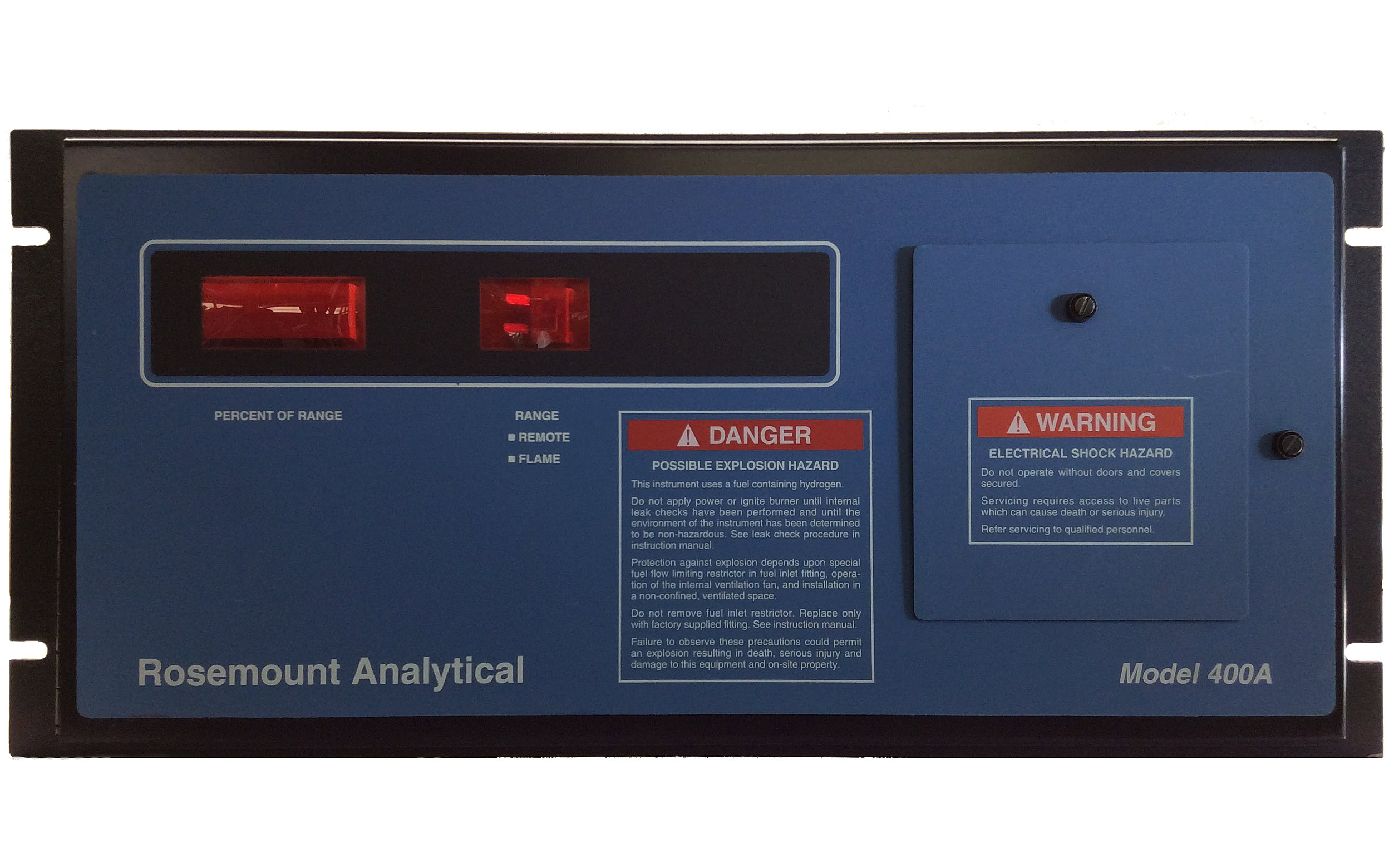
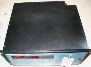
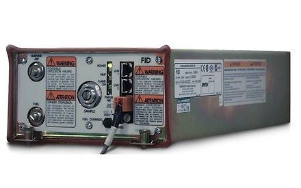
The 400/400A is a Total Hydrocarbon (THC) gas analyzer utilizing the flame ionization detection (FID) method of analysis. This analyzer has been replaced by the newer 400A circa-2009. It’s an older style analyzer (see history tab) that has proven itself to be a 24 / 7 / 365 workhorse for process gas analysis. It is mainly a desktop analyzer (with four rubber feet) or panel mounted analyzer (no feet) that fits in a standard 19″ rack.
The analyzer runs on 120vAC / 60Hz and consumes approximately 125W at steady-state (mainly due to an internal case heater). The analyzer is warmed to help control stability of the analysis (using the theory that as long as the analyzer is controlled at a temperature higher than ambient then thermal stability is assured).
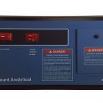
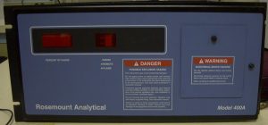
The analyzer had three major revisions. [1] standard 400A with a notch in the case where the process connections attach; [2] standard 400A with a square (rectangular) case (no notch where the process connections attach); and [3] new version of the standard 400A with a square (rectangular) case (no notch where the process connections attach) but with completely new circuit boards operating off of an internal 24vDC power supply.
ANNOUNCEMENT: As of September 30, 2023, the Rosemount 400A has been officially obsoleted by the OEM (Emerson – Rosemount Analytical) with NO OEM PARTS or FACTORY SUPPORT. There is good news though; RIGAS plans to support this analyzer for at least the next ten (10) years, and maybe longer. If you are an end-user, you can help us help you by NOT throwing away good components (boards, regulators, etc.). Everything is repairable. Look at the GENERAL tab for a bigger treatment of this announcement.
Gen
Dimensions 8.75 in. High, 18.75 in. Wide, 15.88 in. Deep
(15.25 in. deep behind the faceplate / starting at the rack frame)
As of September 30, 2023, the Rosemount 400A has been officially obsoleted by the OEM (Emerson – Rosemount Analytical) with NO OEM PARTS or FACTORY SUPPORT. There is good news though; RIGAS plans to support this analyzer for at least the next ten (10) years, and maybe longer. If you are an end-user, you can help us help you by NOT throwing away good components (boards, regulators, etc.). Everything is repairable. Here are a few examples:
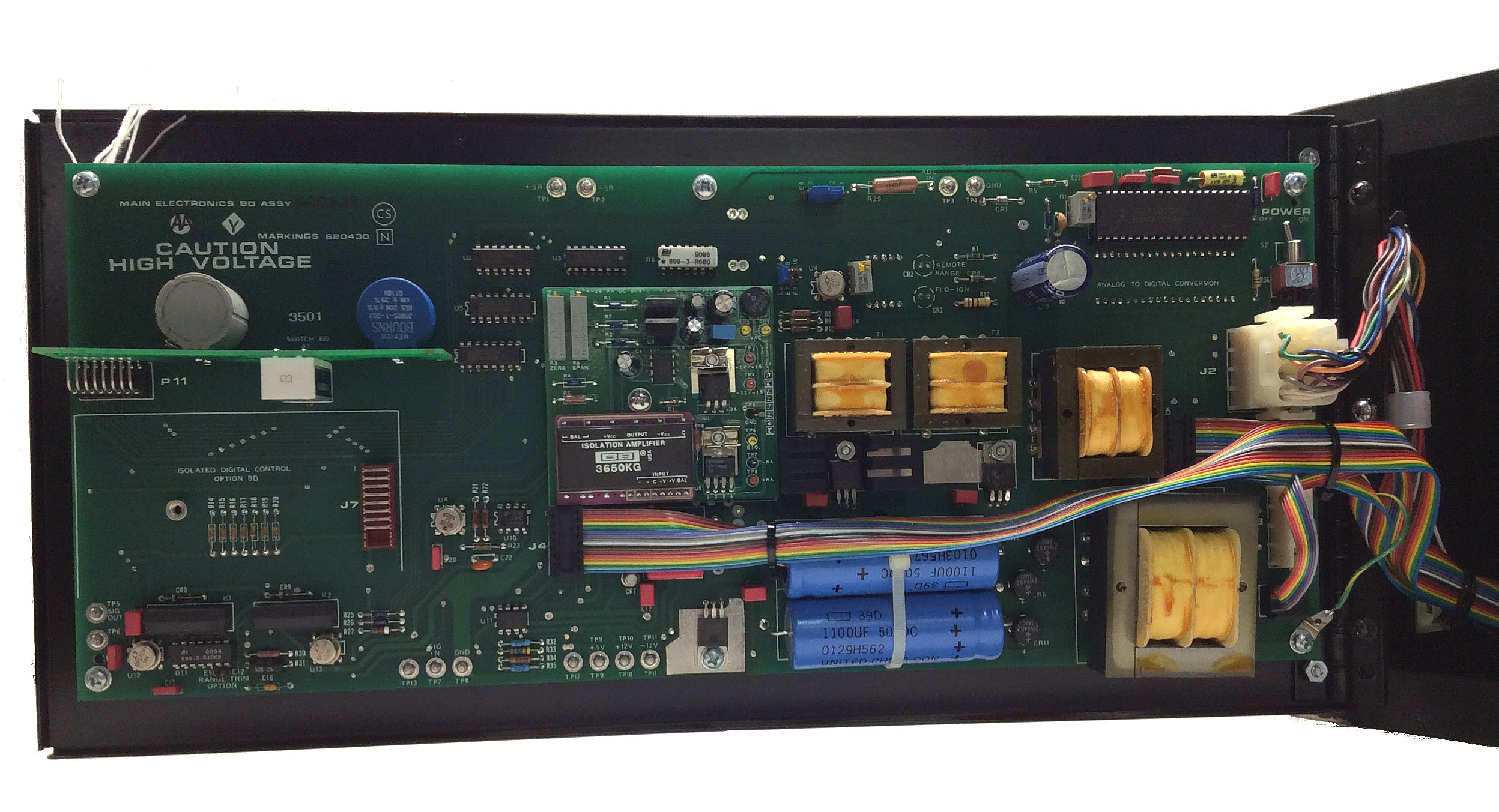
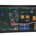
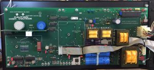
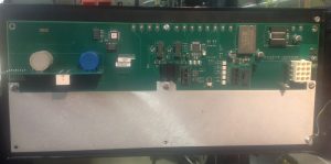
1. Main Electronics Board (pre-2009 vintage) – rarely fails. Shipping sometimes causes the big transformer to be ripped off the board
• Fixable. We have new transformers.
2. 4-20 mADC card gets noisy or fails outright
• Usually a few capacitors dry out causing the “charge pump” to misbehave. We replace the capacitors and fully test the board (includes linearity checks).
3. Backpressure regulator – the rubber diaphragm dries out, becomes brittle, and then it doesn’t regulate pressure very well.
• We install a new diaphragm and relap the valve seat; the result is near PERFECT operation (very little seat leakage and great pressure control).
4. Ribbon cables – they get pinched or scraped.
• We build our own cables.
5. Sample capillary – it gets clogged over time causing a lack of sensitivity.
• It can be cleaned but we’d rather just replace the old capillary (and possibly reuse your old fitting); capillaries are just soldered into a Parker-Hannifin, tube-end reducer, stainless steel fitting using a Silver bearing solder.
• Additionally, if your application is unique, we can build a unique capillary.
6. Thermal insulation – it becomes unglued.
• We replace the insulation where needed and/or reglue the old insulation.
8. Burner contact gets old and brittle, and eventually breaks causing a total loss of analyzer functionality.
• We make our own burner contacts (a.k.a., Hot Dogs).
So, in other words, just about everything is repairable. So, let’s partner up and keep your analyzer running!
A side note: Emerson-Rosemount does NOT have a replacement analyzer for the 400, 400A series. RIGAS is toying with the idea of building a replacement analyzer and calling it the RIGAS 400R. It will be VERY similar to the Rosemount 400A but maybe a little easier to operate. We plan to change the display to read “ppm” rather than percent (%) of scale. It will also have built in diagnostics for those key parameters that we always ask you about when you call in for technical support. In the meantime, RIGAS does recommend the Teledyne 4020 THC analyzer (or one of the sister units, like the 4040).
The 400A Flame Ionization Detector (FID) THC analyzer tests for the presence and concentration of HC compounds in a continuous gaseous sample by combining the sample with a fuel gas stream, ionizing the present hydrocarbons through combustion, and then measuring proportional charge produced by the presence of the ionized hydrocarbons in the sample.
A Flame Ionization Detector (FID) analyzer tests for the presence and concentration of select compounds in a gaseous test sample by ionizing the compound of interest with a controlled combustion reaction.
Total Hydrocarbon (THC) is a measurement of the hydrocarbon content (aggregated, not specific to an individual HC compound) concentration in a measured sample.
Short operational overview video (In works)
In-depth overview video (In works)
Hist
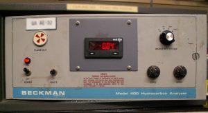
First, there was the Beckman 400. This unit dates back to the 1970’s; it sported a heavy duty metal case, an analog meter, a bull’s eye flame status indicator, and the necessary electronics.
[Beckman 400 from original manual]
[Beckman 400 with newer, upgraded, digital display]
Second, came the Beckman 400A with new electronics, a better preamplifier board, and a notched case (the fuel solenoid is exposed and hangs out the back). It was quickly renamed Rosemount 400A as this was during the transition of when Emerson/Rosemount acquired Beckman Industrial.
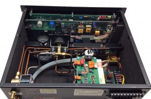
The third revision is our favorite, the Rosemount 400A (square case; no notch). This has the standard Main Electronics Board (one of two possible versions), the better Preamplifier Board (only one tried and true version that we know of), the better case heater assembly (a fan, heater, and dedicated proportional controller circuit board, and one of three versions of the Flame Safety Board.
The last version, the fourth and present version, sports miniaturization of the Main Electronics Board, 4-20 mADC daughter board, and case heater controller board. Everything is driven by a 24 vDC off-the-shelf DIN mounted power supply. The result was the Rosemount 400A . . . We know, it’s confusing. That’s why we call it the “Rosemount 400A-circa 2009 analyzer.”
What’s next? How about the Rosemount 400R? It’s the 400A but enhanced and built by RIGAS but sold through the vast Rosemount sales channels. You’ll have to ask your local Rosemount Sales Rep to ping on his upper management in order to make the 400R something to purchase. You’ll like it – it will have the same great little burner, same Brooks pressure regulators, same Siemens-Moore Products backpressure regulator, similar pneumatics, and the same Rosemount Preamplifier Board. But beyond that, RIGAS is going to fully digitize the Main Electronics Board so that it can read out in percent of scale (as it presently does) or parts per million (ppm) of any hydrocarbon molecule that you can think of. It will also have diagnostics to give the user some insight as to what’s occurring within the analyzer (temperatures mainly but pressures and key voltages too).
This is meant to apply to the Rosemount 400, 400A, NGA-FID, NGA-HFID, and other Rosemount FIDs but it can also apply to other manufacturers.
When your analyzer has these symptoms:
1. was working before
2. shows that the flame is lit
3. does NOT respond to process gas (sample) or span gas (upscale gas)
4. flames out easily
. . . then you probably have a false flame.
The Rosemount analyzers require the flame to be “seated” on the burner jet in order to measure the ion current generated by the burning of hydrocarbon molecules. If the flame is dancing above the burner jet then the ion (measuring) current loop is broken (because one of the terminals of this current loop is the metal tube in the center of the burner jet).
This fix could be simple (version #1): extinguish the flame, and then relight it.
This fix could be simple (version #2): measure the flame temperature; it should be between 30 and 150mVDC; a false flame reveals itself at something more than 200mV. Extinguish the flame and then relight it.
► On older analyzers (120vAC version) the flame signal can be read at TP13 (use TP8 as ground reference).
► On newer analyzers (120vAC version but with an internal 24 vDC power supply) the flame signal can be read at TP3 (use TP15 as ground reference).
If the simple fix doesn’t work, or you experience this false flame regularly, then you probably have a defective burner jet (most likely caused by fouling at the point where the fuel and sample exit the jet tube). A fouled jet can swirl the fuel-sample gas so violently that it can’t light properly. Replacing the burner jet will be required; RIGAS has new burner jets.
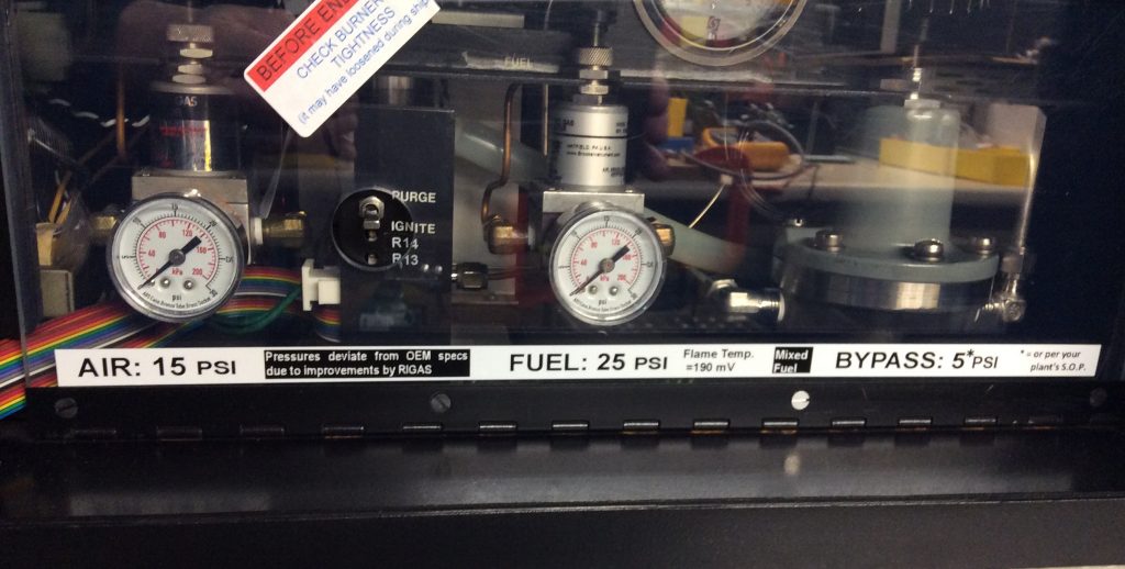
Some of the activities that we perform on your analyzer include replacing the restrictors (and/or capillary). We’ve adopted the “Teledyne API” method of installing good restrictors but not ‘exact’ restrictors. By that I mean, we buy restrictors that meet a small tolerance range, but each restrictor behaves just a little different from the other. Rather than tossing out restrictors that are not EXACTLY on target, we install them in your analyzer, adjust the upstream source pressure to achieve the desired results, and then create a label (or placard) that says what pressures we tuned the analyzer to.
Let’s do a “for instance” discussion. So, under the old way of thinking, the 400A had to run at 15 psig for air, and 25 psig for fuel. When it wouldn’t light or stay lit at 25 psig fuel, you blamed the restrictor(s) (logically), and ordered a new one for about $500. Under “our” way (the Teledyne API way), your analyzer can operate at any pressure that works easily with the physical characteristics of the restrictor that is installed. AND, we’ll give you assistance to adjust the baseline pressure when the restrictor begins to show signs of fouling. Case in point:
1. Your 400A needs to be serviced
2. You send it to RIGAS for repair / overhaul
3. We find that:
• the air restrictor flows weak at 400 cc/min @ 15 psig but flows at specification at 18 psig . . . we’re not going to replace this ‘good’ working restrictor
• the fuel restrictor flows weak at 60 cc/min @ 25 psig but flows at specification at 30 psig . . . this is the top end of your pressure gauge so we need to replace the restrictor
4. We install a new fuel restrictor that performs nicely at 20 psig
5. We calibrate your analyzer at these new pressure values:
• air = 18 psig
• fuel = 20 psig
6. We affix our calibration sticker (see picture below)
7. We affix our optimized pressure settings sticker (that says that these pressure settings override the OEM’s pressure settings from the manual)
8. We send your analyzer back to you . . . and it performs marvelously for five to ten years
9. If necessary, add a little air (that is, adjust the pressure regulator higher)
10. If necessary, add a little fuel (that is, adjust the pressure regulator higher)
• On this one, look at burner temperature. We usually find that 60 to 120 mV on the Flame Temperature signal works best. 60mV is hot but not too hot. 120mV is a somewhat cool flame temperature but not too cool.
► On older analyzers (120vAC version) the flame signal can be read at TP13 (use TP8 as ground reference).
► On newer analyzers (120vAC version but with an internal 24 vDC power supply) the flame signal can be read at TP3 (use TP15 as ground reference).
• And if you’re wondering, the flame safety circuits (some call it “flame confirmation”) trip at 1000mV as it heats up and 1200mV as it cools down
Discussion: there’s actually nothing magical about Rosemount’s firm (sometimes rigid) stance on exactly 15 psi for air and exactly 25 psi for fuel. It really boils down to what settings are optimum for this (your) particular and unique analyzer. And ‘yes’, unique applies to every analyzer ever built as each restrictor flows just a little different than another; each thermistor temperature sensor responds just a little different from another; so, your analyzer may ‘look’ like every other 400A but in reality, it’s not ‘exactly’ the same. There’s another good analyzer manufacturer that subscribes to this thinking (we actually copied their policy), that is, every analyzer that they sell gets a sticker that defines the optimum settings that the technician doing final assembly and testing empirically determined. By you (the end user/customer) adopting this methodology with us, you’ll save on your operating costs. Why? Because you won’t be buying needless parts when, for instance, the fuel restrictor fouls a little bit. You’ll recognize the symptom and simply increase the regulator pressure to compensate for the minute fouling. You’re welcome.
A safety note: there is one restrictor that needs to be maintained ‘at or below’ its design specification, that being the bulkhead fuel restrictor (located upstream of the fuel shutoff solenoid). This restrictor is there to prevent a major fuel leak within the analyzer (fuel solenoid compromised, fuel line cracked, fitting loose, etc.) from creating an explosive mixture. This may be the most critical component in the FM (Factory Mutual) certification. Please don’t bypass this restrictor element. This restrictor can foul significantly before it impacts analyzer operation; and even if it does foul, just increase source pressure from the requested 45 psig to 50 psig (or whatever seems to alleviate the problem). The bulkhead restrictor fouling can be loosely determined by observing the fuel pressure response when you go to light the analyzer. Normal operation: go to “Purge” … the pressure jumps up to 18 psig fairly quickly (almost instantaneously) then gradually reaches the target pressure. Fouled operation: go to “Purge” … the pressure maybe jumps up to 10 psig fairly quickly (almost instantaneously) then gradually reaches attempts to reach the target pressure but never does. By the way, the “fouled operation” description ALSO applies to a leak downstream (or upstream) of the pressure regulator so ALSO check for fuel leaks.
This is a short list of activities that we perform on your analyzer:
1. First, we do AS-FOUND testing
• Does it power up?
• Does it light?
• Does it respond to calibration gases?
• Does the case heater work?
• Does it seem to be contaminated?
2. We extract all of the restrictors and the one capillary, and test them for performance against the OEM’s specifications.
3. We do a clean up of the interior
4. We repaint the lid
5. We update the Preamplifier Board with new wires and connectors
6. We replace ribbon cables
7. We replace out-of-specification restrictors / rebuild the sample capillary
8. We reassemble, light, test, calibrate, and run for 24 hours on a data acquisition trend
9. We attach calibration stickers and optimized pressure settings stickers
10. We write up a service report
11. Then it’s boxed up and shipped according to your specifications
If you get the analyzer back and find that something is not quite right, PLEASE CALL US. It could be as simple as a loose burner cap, or ribbon cable came loose … something out of our control after it leaves our facility.
We sincerely appreciate your business and trust in our company.
Here’s a little background (with respect to mixed fuel analyzers only):
1. When the analyzer is in pristine (new) condition, the zero potentiometer is almost at 10 turns (100%) on the duodial (turns counter). This is where the electronic compensation (for contamination) is at a MINIMUM. Rosemount designed it this was so that turning the pot CCW also caused a decrease in the display value (it’s a little easier for the human brain to comprehend, that is, going CCW causes something to decrease).
2. We release repaired analyzers with the zero pot anywhere from 5 turns (50%) to 9.8 turns (98%); we strive to get the highest reading possible (which implies minimal contamination)
3. RIGAS usually upgrades the 400A Preamp board by replacing the unshielded burner signal wire with a coax (shielded) wire. This helps reduce noise but also makes the signal so clean that we have to install a special potentiometer to inject a small biasing signal. [link to R20 modification]
Here’s a little background (with respect to pure fuel analyzers only):
1. When the analyzer is in pristine (new) condition, the zero potentiometer is anywhere between 5 turns (50%) and 8 turns (80%) on the duodial (turns counter). The pure fuel analyzer is WAY more sensitive so any minor contamination easily shows up and needs some zero pot to compensate. 10 turns (100%) is where the electronic compensation (for contamination) is at a MINIMUM. Rosemount designed it this was so that turning the pot CCW also caused a decrease in the display value (it’s a little easier for the human brain to comprehend, that is, going CCW causes something to decrease).
2. We release repaired analyzers with the zero pot anywhere from 4 turns (40%) on up; we strive to get the highest reading possible (which implies minimal contamination)
3. RIGAS usually upgrades the 400A Preamp board by replacing the unshielded burner signal wire with a coax (shielded) wire. This helps reduce noise but also makes the signal so clean that we have to install a special potentiometer to inject a small biasing signal. [link to R20 modification]
When a 400A (or any hydrocarbon analyzer) won’t zero, do these checks:
1. Read flame temperature. It should be around 100mVDC.
• if it’s <50mVDC then you're probably running hotter than you should be. Decrease fuel pressure and watch for the change in zero reading.
• if it’s <5mVDC then you're probably running VERY HOT and in danger of melting the Teflon burner jet. Decrease fuel pressure ASAP.
2. Alter fuel pressure to see if a few pounds pressure changes the reading (there will be a change as talked about above but it should be slight).
• if the change is significant, you may have contaminated fuel.
• if the change is significant, you may have the WRONG FUEL. A cylinder of 40% hydrogen / 60% Nitrogen (or Helium) is NOT THE SAME as FID ION FUEL (40% hydrogen / 60% Nitrogen (or Helium)). FID ION FUEL has a cylinder assay where the hydrocarbon contamination is VERY low, maybe even listed as “undetectable”.
3. Alter burner air pressure to see if a few pounds pressure changes the reading (there should only be a MINIMAL change, if any). This statement is null and void if your analyzer is running right at the stoichiometric point such that decreasing pressure affects the actual flame due to oxygen starvation.
• This problem will sneak up on you with an aged analyzer as the air restrictor clogs up over many years of service; you’ll set the air pressure to 15# (per the OEM manual) but the burner won’t actually be getting the prescribed 450 cc/min of burner support air.
• An analyzer running at stoichiometric will be hard to zero and hard to span.
4. Alter sample pressure when flowing zero gas. You should expect some variation in the readings but nothing significant. If the reading does change by a huge amount then sample line contamination is almost guaranteed.
• If your process contains a ‘sticky’ hydrocarbon molecule such as Toluene, then expect significant delay times to achieve a good zero as it will take time for the Toluene molecules to detach from the sample transport tubing walls.
Further questions about day-day operation of your 400A can be answered with use of the RIGAS 400A Calculator, this can be found on “The RIGAS 400A Calculator” tab next to the “Troubleshooting” tab on this page.
RIGAS is equipped to diagnose and repair 400A analyzers in our Wooster, Ohio, office.
Please inquire for terms and instructions to ship your analyzer to RIGAS for service or repair.
This symptom shows up in different ways: The readout shows an upscale reading with no flame present:
This unexpected reading is usually indicative of electrical leakage within the burner assembly.
The analyzer displays a loss in sensitivity, i.e, the same concentration of test gas reports a lower measured concentration over time:
This is often indicative of regular system degradation over long periods of time; the fuel and air supply systems (filters, restrictors, etc) as well as the sample restrictor and capillary can develop clogging, and the electrical elements of the burner can be partially short circuited, by extended operation without cleaning and rebuilds on the pertinent systems.
Failure of the burner to ignite can be attributed to several separate (or contributing) factors.
Ignition failure can be due to issues with the supply gases: an insufficiently purged fuel supply, pressure regulators for the air and fuel supplies adjusted incorrectly or simply malfunctioning, or flow restrictions of the fuel and/or air into the burner assembly caused by clogging.
It can also be caused by internal electrical problems, such as faulty contacts and connections in the ignition circuit.
Finally, it may be caused by malfunctioning or failed components, such as the igniter itself, the transformer circuit, or the ignition switch.
The “+1” reading is indicative of an out-of-scale sensor response.
The 400A readout is a “percent of scale” display, which means that the display reads out the percentage of the scale of readings available under the current range setting.
If the analyzer’s current output voltage exceeds 200% of the current scale, the readout will return “+1”.
A quick check of the actual current sensor output is to increment the current range selected upward until the sensor output is no longer out-of-scale. The set range multiples* (see: 400A Calculator) are instructive in determining the real sensor reading.
*Range multiples are variable if the optional 400A range trim board is installed.
Unstable or noisy readings may be symptomatic of a contaminated flow system. Hydrocarbon contamination can occur in multiple areas: external components, like the fuel or air supplies, external frits and filters, regulators or supply tubing; internal flow components, such as pressure regulators and gauges; and finally, with water or condensation infiltration of the burner itself.
Contamination issues can be mitigated with intensive cleaning of the suspect components, or with their replacement.
Keywords: Rosemount 400A troubleshooting
The RIGAS 400A Calculator
The 400A Calculator is an interactive MS Excel spreadsheet for use in determining optimal operational parameters, settings, and expected readings, given user-entered details of the use application. The 400A Calculator spreadsheet is available for download below; please view the tutorial video for instructions on using the spreadsheet.
Download the 400A calculator here 400A_THC_response_calculator_r1
— 400A Calculator Video Tutorial (in production circa April 2022)